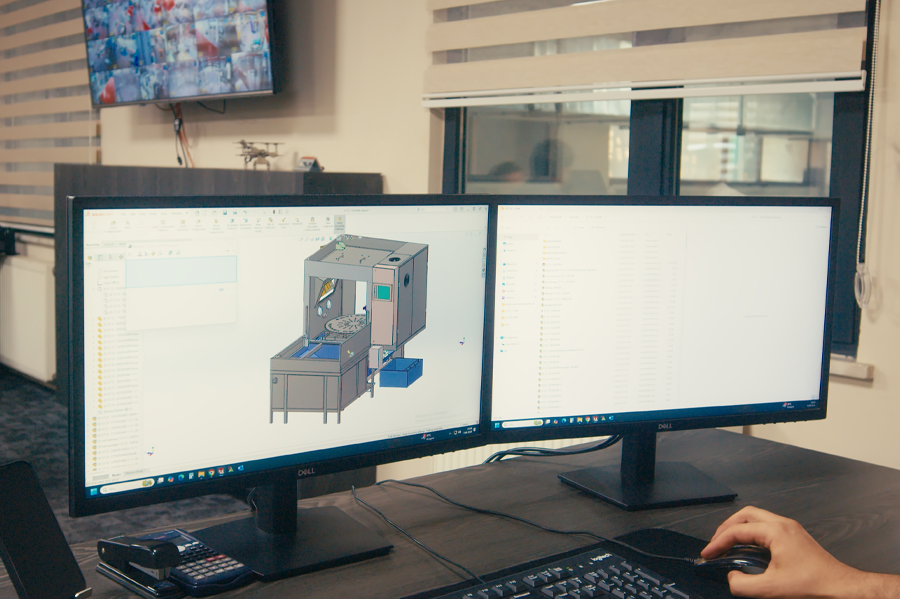
As SLS Industrial, our engineers draw your products in 3D using the SOLIDWORKS programme, carry out checks and prepare them for production. Our R&D department works with full dedication to achieve minimum error and maximum efficiency.
The products requested by our valued customers are first drawn in 3D and submitted for your approval. Afterwards, the necessary checks and final approvals are obtained before moving on to the production phase.
In addition to SOLIDWORKS, our company also uses programmes such as Autocad and Metalix to ensure that products to be cut are processed and delivered with minimum waste.
3D modelling provides high-level presentation in functions such as creating equipment layouts, routing pipes and ducts, locating structural units, allocating service areas and completing projects by laying electrical cables. The software also takes care of the rest: it checks for collisions and displays connections according to diagrams.
It stores units for further use and checks the compatibility of components. Documentation can be extracted at any point during the project. Various drawings and sketches can be created. Similarly, project tracking data can be exported at any time for project reviews.
In addition to piping, cable tray, electrical and structural design, 3D layout offers change by creating 3D parametric components. Parametric 3D models with service area reservations can be edited directly in 3D. It offers the advantage of online and case-based collision detection.
Comprehensive standard and component libraries are available. Simultaneous and unlimited multi-user environment allows wide-area use. It is effective in replicating projects for efficient use of resources in globally distributed environments.
Pre-defined structural units allow easy creation of repeatedly used structures. Designers can specify types and standards of units such as platforms, walkways, lattices and stairs. They can then place these in the model. All necessary construction data, including MTOs, construction drawings and others, can be automatically extracted.
It is an integrated solution for seamless use of data from laser scanners in 3D designs and construction data. It increases the use of laser scanning technologies in design projects. You can use point clouds directly in the 3D design tool using familiar design tools.
It provides the ability to view and examine an existing facility layout while drawing a new plan. It allows the use of point clouds as a reference for measurement and placement when designing new elements in detail or reshaping existing ones.
It reduces the time for surveys, operational downtime at the customer's facility and the need for site visits in potentially hazardous environments. It prevents rework reduction due to fewer unknowns and assumptions about existing structures and immediate availability of accurate dimensions and spatial geometries. The scope of changes can be quickly estimated. There is no need to worry about the lack of built-in electronic documentation available from the operator.
It is all you need to succeed in projects, reduce CAD licence costs and improve design quality while benefiting from remote work sharing. It can be defined as the process of creating a three-dimensional digital visual representation of a real object by incorporating real-time data into the model and using dedicated CAD software that interacts with the object, which can be rotated, inverted and exploded. It can also be manipulated in any way on screen.
A wireframe model is a skeletal description of a 3D object. There are no surfaces in a wireframe model. It consists only of points, lines and curves that define the edges of the object. Since each object making up a wireframe model needs to be drawn and positioned independently, this type of modelling can be the most time-consuming. Surface modelling is more complex than wireframe modelling because it defines not only the surfaces but also the edges of the 3D model.
A surface modeller defines oriented surfaces using a polygonal mesh that can approximate curved surfaces. Solid modelling is the easiest type to use:
3D objects can be made by creating basic 3D shapes such as boxes, cones, cylinders, spheres, wedges and tori. These shapes are then combined, subtracted or combined by finding overlapping volumes to create more complex solids. Solids can also be created by sweeping a 2D object along a path or rotating it around an axis.
3D design can be used in almost every sector, including educational purposes such as consumer products and even schools. When used in engineering, such as prototypes or building designs, or in an architectural context, solid 3D design offers an exact likeness of how the final object will look and work in a real-life scenario.
The same applies to other fields of study such as biology or chemistry, where 3D models are used as visual representations of body organs or the chemical structure of an atom. It is used to bring the object to life and eliminate potential flaws.
It stands for Computer-Aided Design. It encompasses a wide range of design tools used by various industry professionals such as architects, designers, artists, manufacturers and of course engineers. CAD systems help their users by performing thousands of complex geometric calculations in the background without anyone having to think about it. This makes the designer's job much easier and frankly more enjoyable.
CAD started out limited to only 2D capabilities — like drawing on a flat piece of paper. Objects can be designed and drawn using basic views. This gives you a top, bottom, left, right, front, back and angled view called isometric. It essentially worked like drawing something in 2 dimensions on paper. Then came 3D CAD programmes that allowed the user to take these 2D views and pull them from the page into a 3D object on the screen.
It took an advanced dimension, like drawing a 2-dimensional square on a piece of paper and then pulling it from the page into a cube or pulling it into a really long rectangular bar. This is what 3D CAD design allows to be done in a computer programme.
Through layered manufacturing, product designers find the opportunity to design for performance outside of traditional design constraints for assembly or manufacturing. This allows them to achieve what might be less practical using other manufacturing techniques. The only limitation in the use of 3D design, which creates essentially unlimited complex shapes in every size and form, is the user's imagination.
Almost every modern product we interact with daily is created using 3D CAD design. Every product, from the details of cars to TV remote controls, from kitchen utensils to computer mice, is prepared in a virtual environment. The reason it stands out in product design is that it helps reduce costs to a minimum.
When using 3D CAD design, a virtual reality object is essentially created that can have all the same properties as a real physical object. All content such as material, weight, dimensions, optical properties and physical properties allows a virtual object to be created. A model of how the object will behave in the real world is seen even before it is built. This is exactly where things get really interesting and where the maths problems get wildly complex.
3D design can create part assemblies to see how they fit together. It can test how they will react to the forces applied to them. Objects can be dropped to see if they break. The movement and interaction of moving parts within an assembly can be tested. How fluids will flow through them and how they will be manufactured using simulations can be evaluated. In short, it is the environment where near-perfect images are created to see how products will look in real life.
CAD, which stands for Computer-Aided Design, is a process that allows computer users to design various products and geometric shapes on screen rather than creating drawings by hand. Using CAD software, a plan of how the created object will look is drawn up and then created to determine the working system. At this stage, changes to the object can be made easily. CAD drawings are a process in industrial design that also shows the dimensions, processes and materials of an image created by computer. These drawings can be two-dimensional (2D) or three-dimensional (3D).
When an object is drawn in 3D using CAD, the process is often referred to as machining or modelling, while 2D design is often called drafting. CAD drawings are used for numerous industrial and manufacturing applications. They are also particularly common in technology, art and graphic design. This process presents itself as an application that offers more design flexibility for designers and artists than other environments.
These drawings are also used in the development of industrial products and equipment, as well as the automotive and aerospace industries. Many special effects rely on the computer application method created with CAD software. Finally, CAD drawings are a critical component of the construction and engineering trade.
Before CAD was invented, products and their plans were drawn by hand. This process was cumbersome and time-consuming, requiring frequent revisions as well as numerous drawings. With the introduction of CAD software, engineers and designers were able to create and modify their drawings quickly and easily. Design firms hired fewer staff and accelerated design and product development cycles.
CAD software also emerged as an alternative to engineers and designers having to explain to a draughtsman. This allowed them to create their own drawings and bring accurate designs to market. Although it has been in use since the 1960s, CAD software brought cost-effective solutions for many industries until the late 1980s and early 1990s. While the early versions of the software were based on 2D vector design, modern CAD drawings included 3D modelling capabilities.
The 3D modelling software that stands out in today's conditions helps designers not only to draw an object but also to rotate it on an axis. It also allows you to see the walls of the object from the inside. This modelling capability offers useful experiences, especially in engineering and design technology. It allows designers to virtually review a product and explore different angles.
Today, designers have the opportunity to greatly enhance their 3D models with photo-realistic images. This gives designers the opportunity to showcase their work and communicate ideas to clients effectively. Imagining that you are sharing a realistic image with clients rather than a simple model and that it truly delves into the finer details of a design, it can be seen that the result offers faster satisfaction in terms of design. There are applications used for realism here. To briefly look at them;
Rendering: It is the name of the process that converts a 3D model into an extremely realistic image. The images produced are particularly useful for designers, because they show an idea rather than something that already exists. These images give the impression that they are real. This gives clients the opportunity to have a real idea of what the final product will look like. For example, by applying materials such as parquet flooring to a design, a realistic-looking presentation can be achieved. This way, clients can save time and money by making decisions early in the project.
FluidRay: It has many features that distinguish it from other rendering applications and make it the best processing software for designers.
SketchUp compatibility: FluidRay's built-in compatibility with SketchUp allows designers to create 3D models in SketchUp and then easily import them into the FluidRay interface.
Real-Time Design: It enables designs to be adjusted simultaneously by quickly sharing multiple design options. It helps decisions to be made quickly and efficiently to shorten project timelines.
It prevents delays and eliminates processes that would create costs. This ensures effective cost control. It allows problems to be discovered before production begins or material production takes place by making changes at the design stage.
The creation of detailed designs allows clients to better visualise the entire project presented to them. This enables them to sample different elements such as materials, fixtures, paint colours and lighting.
It provides the opportunity to present design ideas and changes to clients quickly and effectively to progress projects by communicating ideas easily. It allows clients to be impressed. You can create eye-catching design presentations that highlight your vision and capabilities that win over even clients who have no demand.
Technology is bringing imagination closer to reality. The best example of bringing this back to life is how 3D modelling has changed the world of presentation for industrial designs. It's like extracting multidimensional images from your brain and painting them on paper to see how they look. The impact of 3D modelling on pre-production presentation is undoubtedly the most transformative thing that has happened. The presentation benefits of the product to be produced from 3D modelling are quite numerous;
Realistic, easy and fast; Tasks such as extracting the scores of the horizontal, vertical and diagonal lines of 2D drawings and obtaining a one-time image of architectural services are what 3D design facilitates. Designs become more vivid. Clients can see industrial products with a virtual eye. They can also quickly check whether a new product is feasible. It provides the opportunity to check how small changes in the design will look.
A picture speaks a thousand words; if you want to understand how much better the industry 3D model is than the 2D model, you can compare the designs and look at the details.
The experience of going through a 3D model is more engaging and satisfying for a potential customer than viewing a 2D drawing. Vivid images stay in the potential customer's mind for longer. This gives you a higher chance of winning the customer. Similarly, it also offers quick approval for industrial products.
In a 3D model, it is easy to see the effect on the overall design after small or large changes have been made. This helps finalise the design without too much cost and without changes and corrections that cause post-construction costs.
It provides the opportunity to show your customers the appearance of the industrial products they want to produce exactly as they imagined. This creates unique experiences in all kinds of industrial design products. A 3D design also offers the ability to show the physical dimensions of objects and the distances in the overall layout.